
Ship Propeller Effects on Sediment Transport
The effects of ship propeller-induced jet flow on sediment transport were presented by Colangeli et al. (2023).
Theory
Efflux velocity
The magnitude of the efflux velocity generated by a propeller was estimated using the empirical formulas given by Hamill and Kee (2016) and Hamill and McGarvey (1997) (NEED UPDATE)
where \(E_0 = (D_p/D_h)^{-0.403} C_t^{-1.79} \mbox{BAR}^{0.744}\), in which \(D_p\) and \(D_h\) are the propeller diameter and hub diameter, respectively. \(C_t\) is the C thrust parameter, and BAR is defined as the thrust and Blade Area. \(n\) is the RPM.
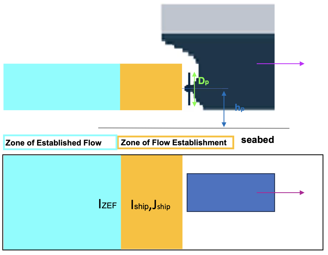
Axial flow distribution (NEED UPDATE)
where (\(x^\prime,y^\prime\)) represents the local coordinates with an origin at the propeller location. \(h_p\) is the height from the axial to the bed. \(c\) is the ducted-parameter.
Note
The axial flow is only used to calculate effects on sediment transport. There is no interaction between the axial flow and ship-wakes.
Propeller effects on bottom shear stress
The propeller effects on the bottom shear stress were incorporated into the calculations of the friction velocity \(u_{*}\) and shear stress \(\tau\).
where \(C_f = 0.01 (C_h/D_p)\).
Model configuration
To incorporate the propeller effects into the sediment transport calculation, you need to compile the program with a flag -DPROPELLER in Makefile. For example
FLAG10 = -DVESSEL
FLAG11 = -DPROPELLER
In input.txt, specify
VESSEL_FOLDER = vessel/
NumVessel = 1
In /vessel/vessel_00001
Title: Vessel # 1
PRESSURE, 1
Length(m), Width(m), Alpha1(m),  Alpha2(m), Beta(m), P(unit)
20.0,  10.0, 0.5, 0.5, 0.5, 3.0
N_revolution,D_prop, C_thrust, D_hub, BAR, H_prop(below deck), C_duct
1.6, 3.7, 0.48, 1.1, 0.55, 2.5, 0.19
Time, X(m), Y(m)  (relative to the orgin of the coordinates)
0.0     100.0   30.0
100.0   1100.0  210.0
Note that the 5th and 6th lines are newly added lines for propeller input. In particular, the 5th line is comment line for parameter definitions, and the 6th line specifies values (float) of those parameters.
Example
An example can be found in /simple_cases/vessel_propeller_effect. Two vessels are specified. The figure below shows the comparison between cases with/without propeller effect.
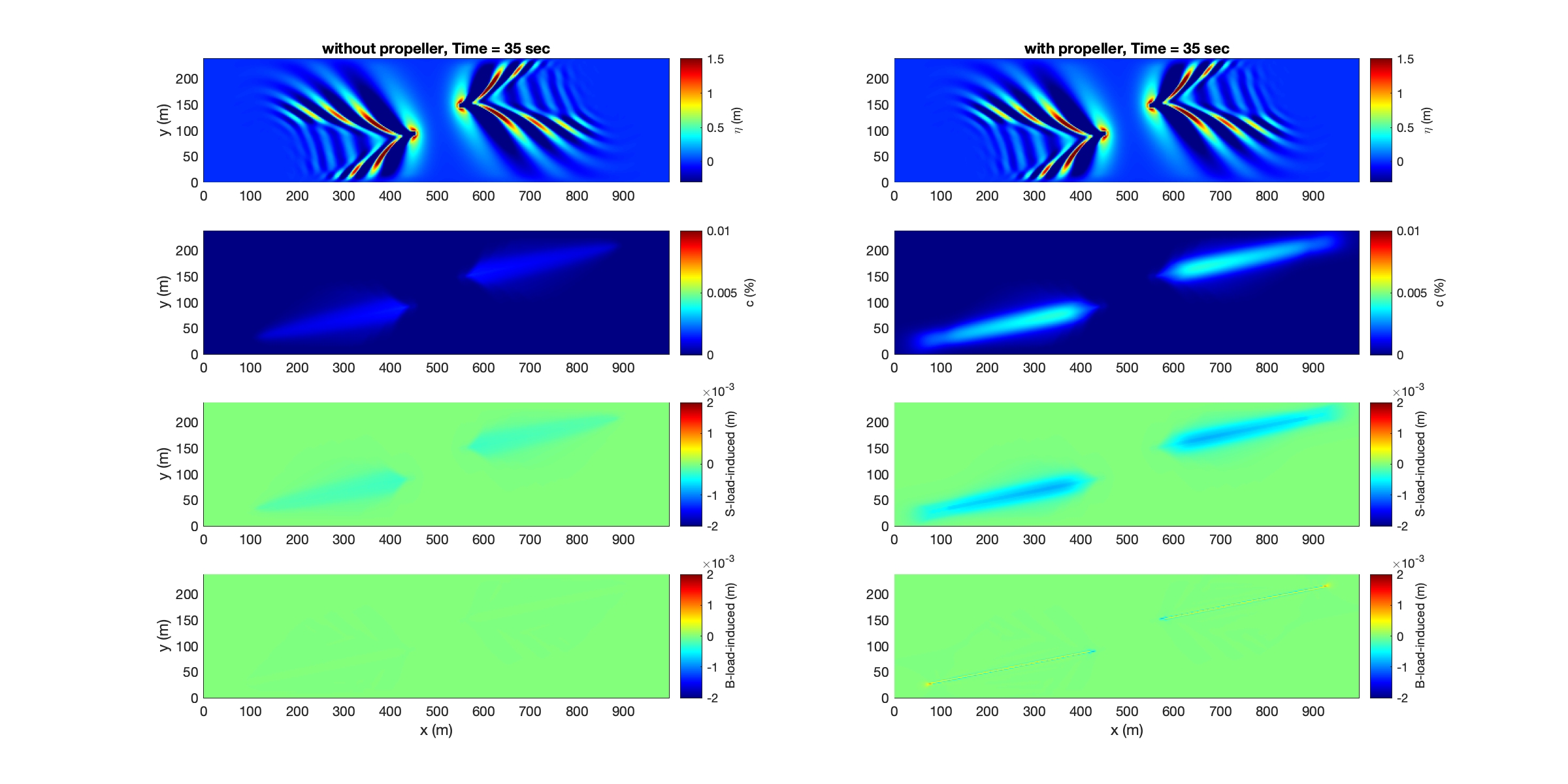
Animation:
Comparison between cases with and without propeller effects
References
Colangeli, C., Leftheriotis, G., Dimas, A., and Brocchini, M., 2023, Ship-forced sediment transport: a new model for the propeller jet flow, The 13th Symposium on River, Coastal, and Estuarine Morphodynamics, RCEM2023, Urbana-Champaign, Sept. 25-28, 2023
Hamill, G.A., Kee, C., Predicting axial velocity profiles within a diffusing marine propeller jet. Ocean Eng. (2016), http://dx.doi.org/10.1016/j.oceaneng.2016.07.061i