Shipwakes
Ship-wake Model Setup
Specify a folder which contains a number of vessel files,
vessel_00001, vessel_00002, ...VESSEL_FOLDER = ./Specify the number of vessels (e.g., 5)
NumVessel = 5In
vessel_00001, for example, provide vessel name, vessel type, vessel length, width, shape parameters, draft and time series of vessel path:Title: Vessel # 1 - (name) PRESSURE, 1 (pressure type, type I) Length(m), Width(m), Alpha1, Alpha2, Beta, P(unit) (comment, vessel parameters) 20.0 10.0, 0.5, 0.5, 1.0 (vessel parameters) 0.0000000e+00, 5.6000000e+02, 5.0000000e+02 (time, x, y) 1.0000000e+00, 5.6374897e+02, 5.0255132e+02 (...) ...
In the time series, the first column is time in seconds, the second and the third are x and y in meters, respectively.
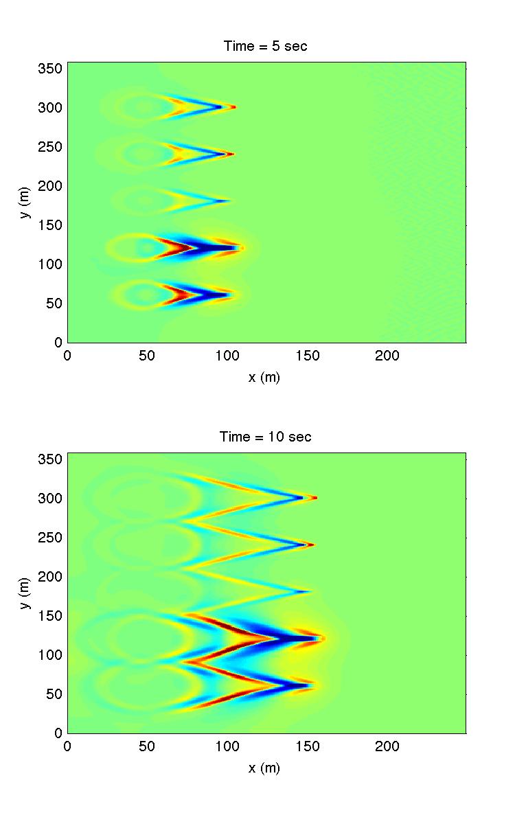
The following is an example which includes 5 vessels of different types
This example can be found in /simple_cases/vessel_types_compare/.
Figure: Vessel types (from bottom to top): 1) Pressure Type I, 2) Pressure Type I with large \(\alpha\), 3) Pressure Type II, 4) Slender Type I, 5) Slender Type II.
vessel_00001: Pressure Type I
Title: Vessel # 1
PRESSURE, 1
Length(m), Width(m), Alpha1, Alpha2 Beta, P(m)
20.0  8.0, 0.0, 0.0, 0.5, 3.0
Time, X(m), Y(m)  (relative to the origin of the coordinates)
0.0    50.0  60.0
100.0 1050.0 60.0
vessel_00002: Pressure Type I with large \(\alpha\)
Title: Vessel # 2
PRESSURE, 1
Length(m), Width(m), Alpha1, Alpha2, Beta, P(m)
20.0  8.0, 0.9, 0.9, 0.5, 3.0
Time, X(m), Y(m)  (relative to the origin of the coordinates)
0.0    50.0  120.0
100.0 1050.0 120.0
vessel_00003: Pressure Type II
Title: Vessel # 3
PRESSURE, 2
Length(m), Width(m), a, b, c, P(m)
10.0  5.0, 16.0, 2.0, 16.0, 2.0
Time, X(m), Y(m)  (relative to the origin of the coordinates)
0.0   50.0   180.0
100.0 1050.0 180.0
vessel_00004: Slender Type I
Title: Vessel # 4
SLENDER, 1
Length(m), Width(m), Alpha1, Alpha2, Beta, F(unit)
10.0  5.0, 0.0, 0.0, 0.9, 12.0
Time, X(m), Y(m)  (relative to the origin of the coordinates)
0.0   50.0   240.0
100.0 1050.0 240.0
vessel_00005: Slender Type II
Title: Vessel # 5
SLENDER, 2
Length(m), Width(m), Alpha1, Alpha2, Beta, F(unit)
10.0  5.0, 0.8, 0.8, 0.9, 40.0
Time, X(m), Y(m)  (relative to the origin of the coordinates)
0.0   50.0   300.0
100.0 1050.0 300.0
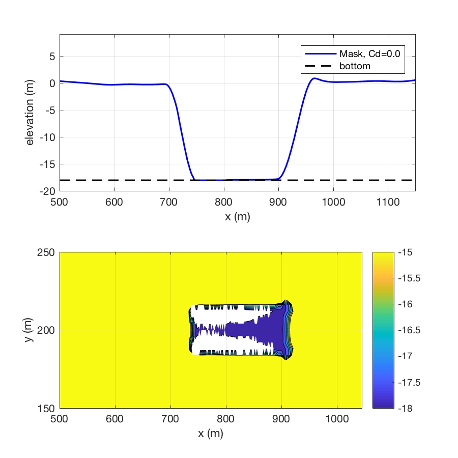
Deep Draft Vessels
An instability problem may occur in Boussnesq modeling a large-size vessel with a draft close to channel depth. We developed three methods in the fully nonlinear Boussinesq model, FUNWAVE-TVD, to suppress high-frequency spikes generated near-field of a vessel. The three methods are the shock-capturing method, friction method, and viscosity method, respectively. Tests show that the combined shock-capturing and friction method is the most effective method to suppress the local high-frequency noises, while it does not affect the far-field solution. A strong test, in which the target draft is larger than the channel depth, showed that there are no high-frequency noises generated in the case of ship squat if the shock-capturing method is used.
Shock-capturing Method The shock-capturing method is used by switching to SWE solver at the bottom of a vessel. The method is consistent with the shock-capturing-based wave breaking scheme. MASK9 is used to mask the area of the vessel bottom, where SWE is solved.
Friction Method The Friction Method is one of the dissipation methods used for damping waves as in sponge layers. A large bottom friction is applied locally at the vessel bottom. A proper friction coefficient Cd can be specified by users.
Viscosity Method The Viscosity Method is also one of the dissipation methods used as in sponge layers. Wave damping rate is usually lower than that in the friction method.
Model Configuration
To use one of the three methods or combined methods, the code needs to be recompiled with the flag -DDEEP_DRAFT_VESSEL in Makefile. The default option (if nothing specified in input.txt) is the combined shock-capturing method and friction method with a friction coefficient of 0.1. This default option and associated parameter were obtained based on the best practice of the tests we have conducted. Users can also specify an option and parameters in input.txt by themselves.
Setup of shock capturing method
MaskMethod = T
Setup of friction method
FrictionMethod = T
CdDeepDraft = <floating-point number>, suggested values: 0.1 – 1.0
Setup of viscosity method
ViscosityMethod = T
VisDeepDraft = <floating-point number>, suggested values: 0.1 – 5.0
Setup of minimum clearance
CLEARANCE = <floating-point number>, default value: 1.0
Examples
The test examples can be found in the github package (master) /simple_cases/vessel_deep_draft/
The figure below shows the result from the strong test in which the target draft is even larger than channel depth. Although the model configuration is not realistic, it can serve as a strong test for numerical instability. Here, a target draft of 20 m versus a channel depth of 18 m was applied. We used the shock-capturing method in the test. The figure shows a large portion of grid cells are dry (white area). The dry points did not cause any high-frequency noises due to the application of the shock-capturing method.