
Example: add partially reflecting/absorbing breakwater
For model setup, refer back to Breakwater and Obstacle.
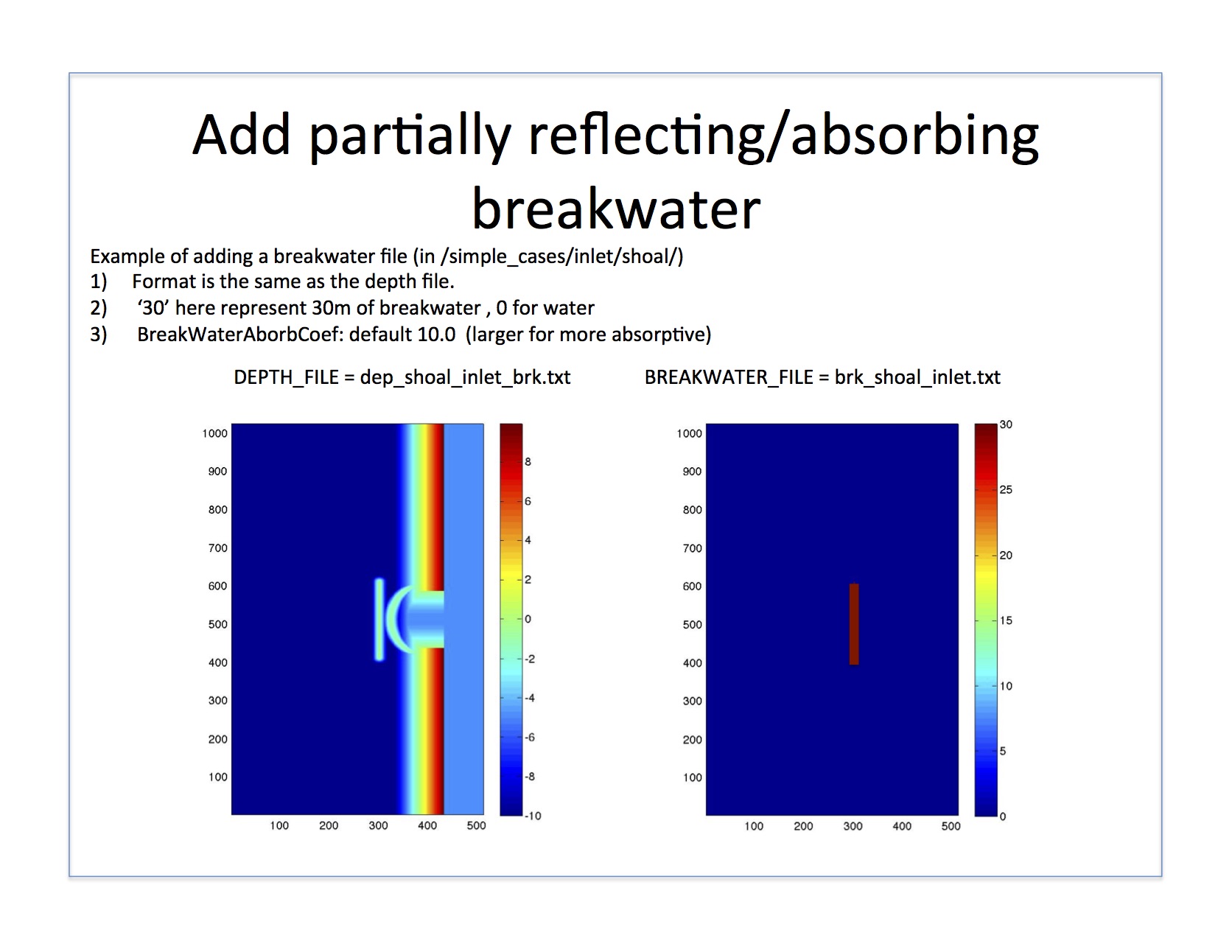
In the BREAKWATER_FILE, non-zero points specify the location and width - or area of influence - of the internal sponge layer. In the below diagram, the grid of 1’s and 0’s represent the breakwater file input, where 1’s are in meters defining the radius of the sponge width. The area of influence, shown here as blue circles, covers up to one grid point in each direction if DX = DY = 1. If DX = DY = 0.5, for example, the area of influence would cover two grid points in each direction with the 1’s at the center. At these grid points, the BreakWaterAbsorbCoef is applied.
